
Projects » Linux alarm clock - Display
View on GitHubThis is the display i made for my alarm clock project. The first version was a 24x7 LED matrix but later changed the design for a four digits seven segment display. I decided to keep the drawings for the LED matrix and named it model A and Model B for the segment display.
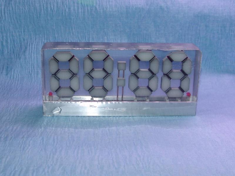
The display is encapsulated in clear casting epoxy and is 5 inches wide by 2 1/4 inches high by 1 inch thick.

I was new to silicon molds and casting epoxy, so there was definitely a learning curve. I was unable to avoid the micro bubbles problem entirely. There are a few, but I can live with it, it’s not that bad. The assembly of each digits PCB, making the segments diffuser, gluing them, etc. takes a very long time. I did not want to start all over because of a few bubbles.
Design process
Sometimes, there is a gap between a design idea and what is realistically feasible. I had the crazy idea to make a clock with a fully transparent seven segment display. I looked into it, turns out such a display already exists and it’s called a transparent OLED or T-OLED. There are transparent display modules available on the market, such as this one from 4dsystems, but it’s size was not practical for this project. While searching for a solution, I found a company that manufactures custom T-OLED display. But they usually deal with large production runs. Producing a single display would cost way too much.
Led matrix display (model A)
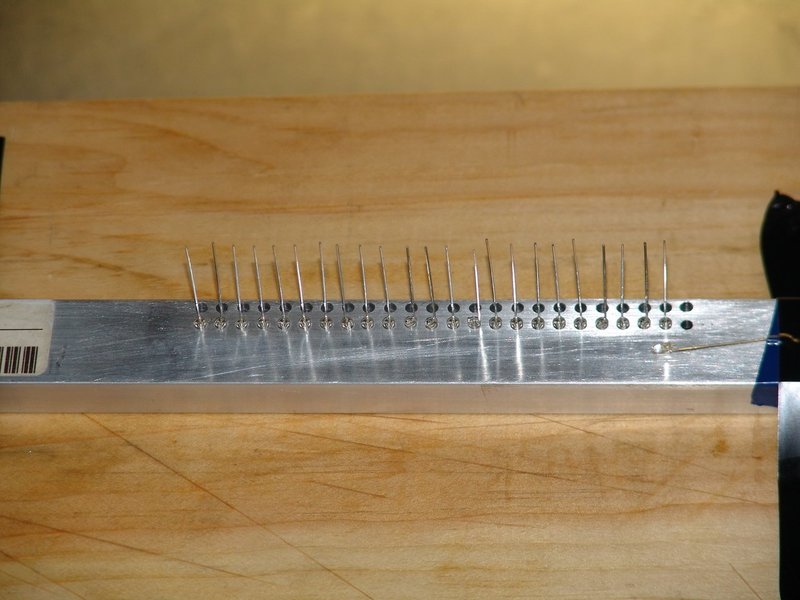
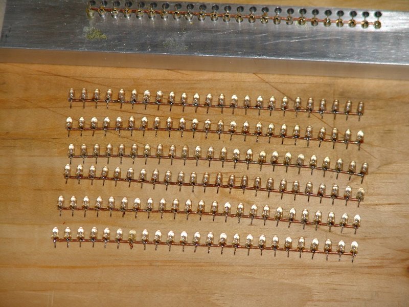
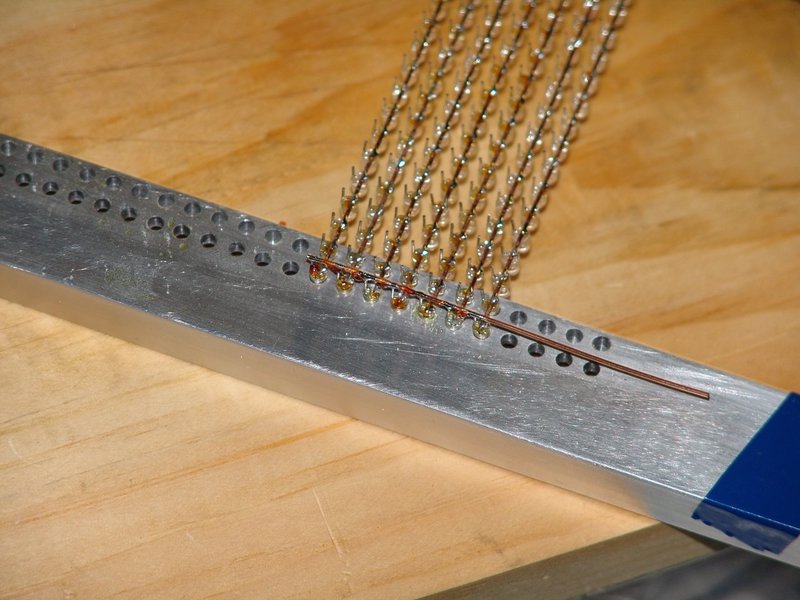
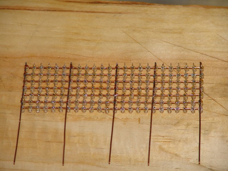
As a compromise, I came up with an LED matrix as the display (24 columns by 7 rows). To retain the transparent effect i wanted as much as possible, instead of mounting the LEDs directly on a PCB, I soldered them in a grid pattern, extending the leads vertically to the PCB located at the base of the display.
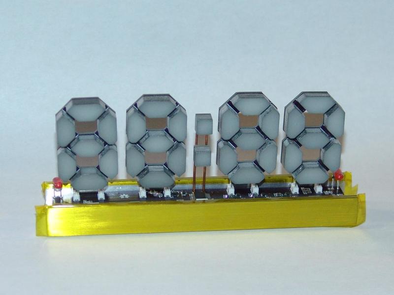
Seven segment display (model B)
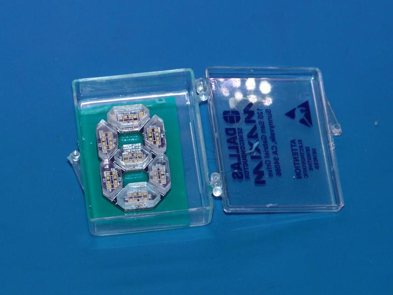
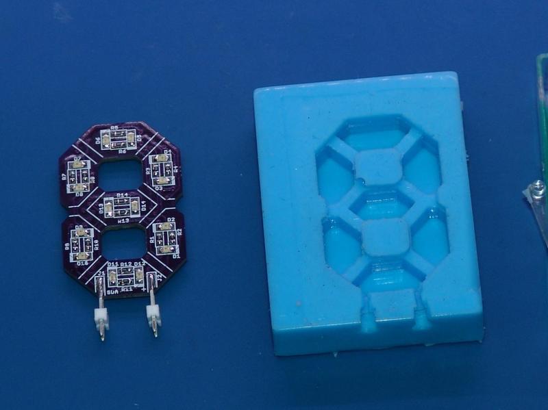
I went back to the seven segment display idea. Instead of using pre-made display modules, I designed my own. Each digit has its own PCB with the shape of a number eight. The segments are comprised of two bright orange LEDs in parallel covered with a white epoxy diffuser.
The digits are 1 inch wide by 1.5 inch high and has 0.3-inch wide segments.


Circuit
The brightness of those LEDs is controlled by a PCA9634 dimmer chip. There is one for each digit plus one on the base PCB which controls the brightness of the two dots, am/pm led, alarm on/off led and the RGB lamp.

This chip communicates with the CPU via I2C and has a 7-bit hardware selectable address. The two lower bits are selectable using a solder jumper on the PCB so that each digit has a unique address on the bus. In addition to the device address, the PCA9634 has 3 sub call address and an all call address. This feature makes it possible to broadcast a single command simultaneously to all the devices present on the bus. Each output has its own 8-bit resolution (256 steps) PWM running at 97 kHz and can also be dimmed globally with the group PWM.
I was hoping to be able to use the blinking feature on the PCA9634 to make the digits flash when I program the alarm. Because the chips are not synchronized, the clock is drifting, but I did not expect it to be this much. It’s fine when dimming the LEDs but in blinking mode, it becomes really noticeable.
There is also a TSL2561 ambient light sensor which I am going to use to automatically adjust the brightness of the segments.
Mechanical drawings
| Dwg ID. | Title |
|---|---|
| CLK-DWG-01 | Led Matrix display board dimensions |
| CLK-DWG-22 | Display (model A) - LED matrix |
| CLK-DWG-23 | Display (model A) - LED matrix PCB assembly |
| CLK-DWG-24 | Display (model A) - Assembly |
| CLK-DWG-06 | Display base |
| CLK-DWG-08 | Display (model B) - Segments PCB |
| CLK-DWG-09 | Display (model B) - Dots PCB |
| CLK-DWG-10 | Display (model B) - Base PCB |
| CLK-DWG-26 | Display (model B) - Segment PCB Assembly |
| CLK-DWG-27 | Display (model B) - Base PCB Assembly |
| CLK-DWG-28 | Display (model B) - Assembly |
| CLK-DWG-29 | Display (model B) - Dots PCB Assembly |
Schematics
| Dwg ID. | Title |
|---|---|
| CLK-SCH-01 | Led Matrix display board (Model A) |
| CLK-SCH-05 | Display (model B) - Segments PCB Schematic |
| CLK-SCH-06 | Display (model B) - Dots PCB Schematic |
| CLK-SCH-07 | Display (model B) - Base PCB Schematic |
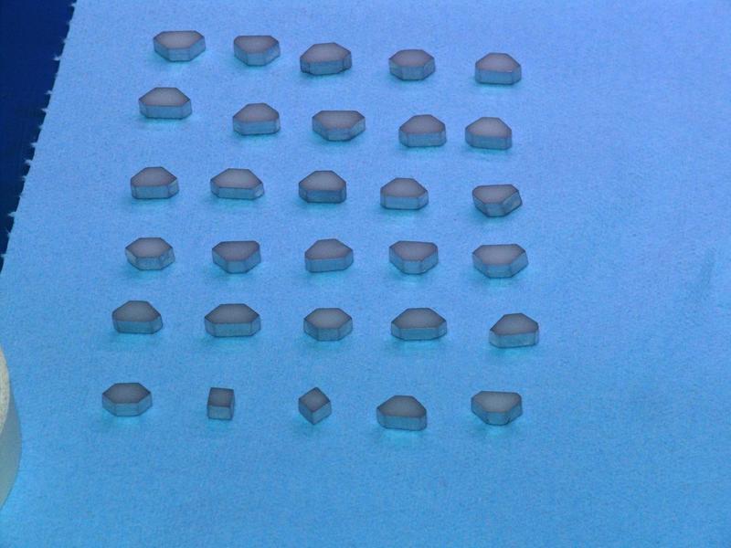
Segments diffusers
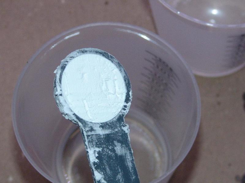
The segments diffuser are made with clear casting epoxy with cornstarch at a ratio of 1 to 4 (25% cornstarch by volume, 75% epoxy). The cornstarch powder is fine enough so that it dissolve very well in epoxy and gives the mix a white translucent color. The key is to mix small amounts of it at a time and making sure the cornstarch is completely dissolved. Undissolved specs of cornstarch are more opaque and becomes visible when you shine a light through it.
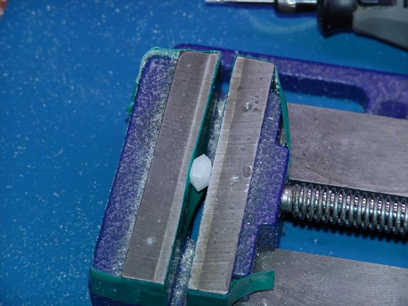
I painted the sides of the diffuser. It makes it easier to see the digits if you look at them at an angle and it also reduce the light spillage to adjacent segments.
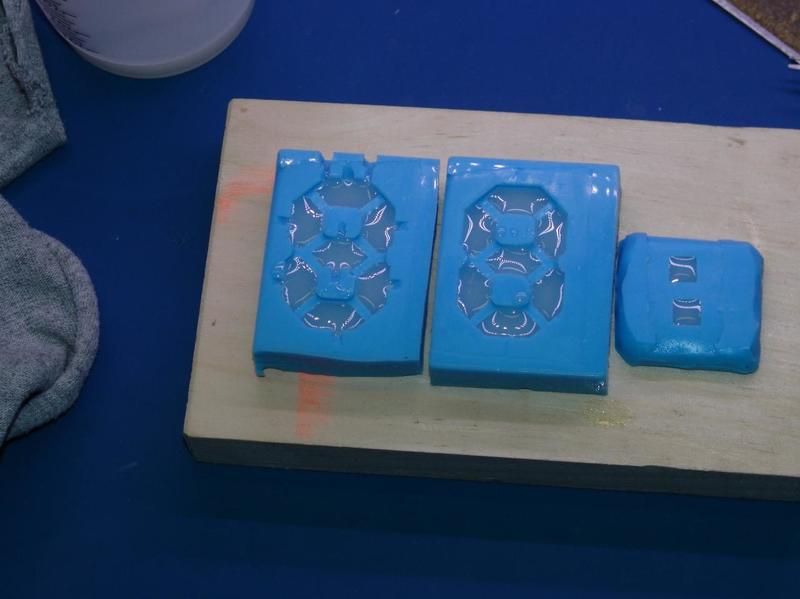
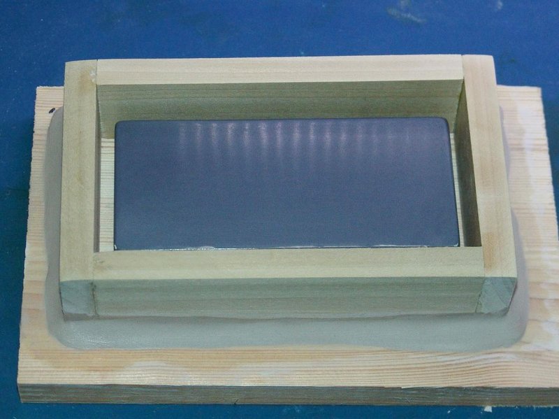
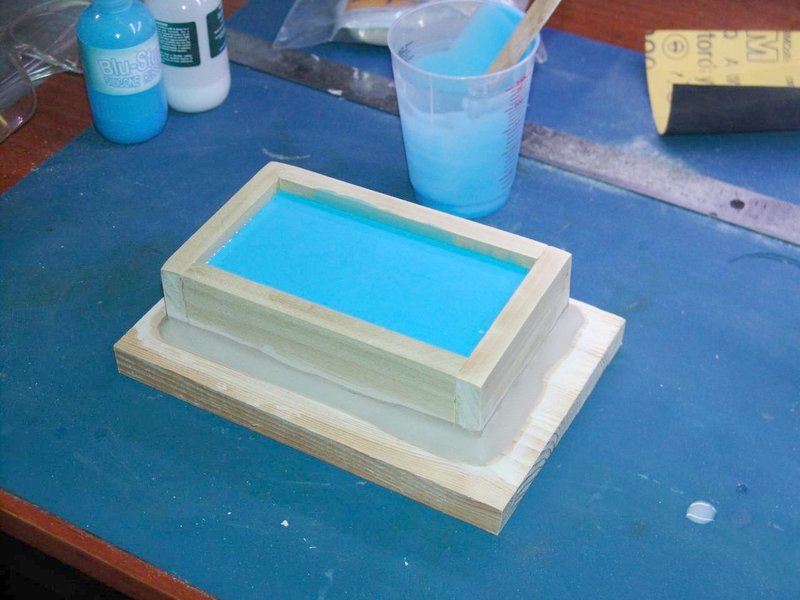
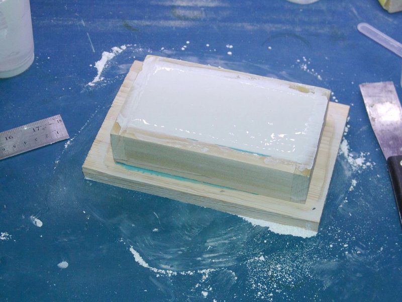
Mold
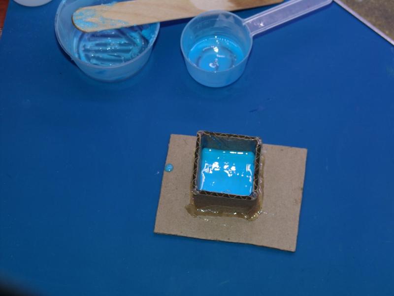
I use the “Blu Stuff” silicon rubber which I found on eBay. It gives pretty good results, but you need to work fast with it. It sets within 5 minutes after you start mixing it, but after 3 minutes, it already starts to solidify a bit.
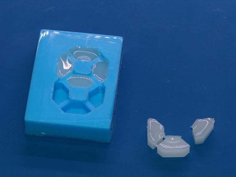
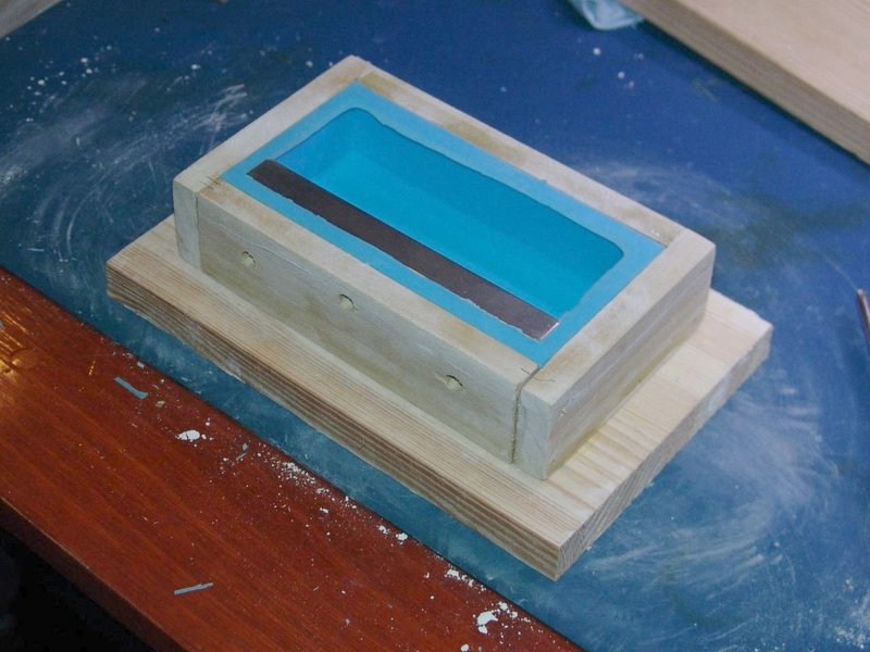
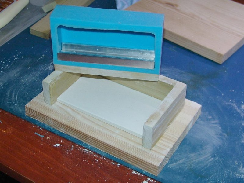
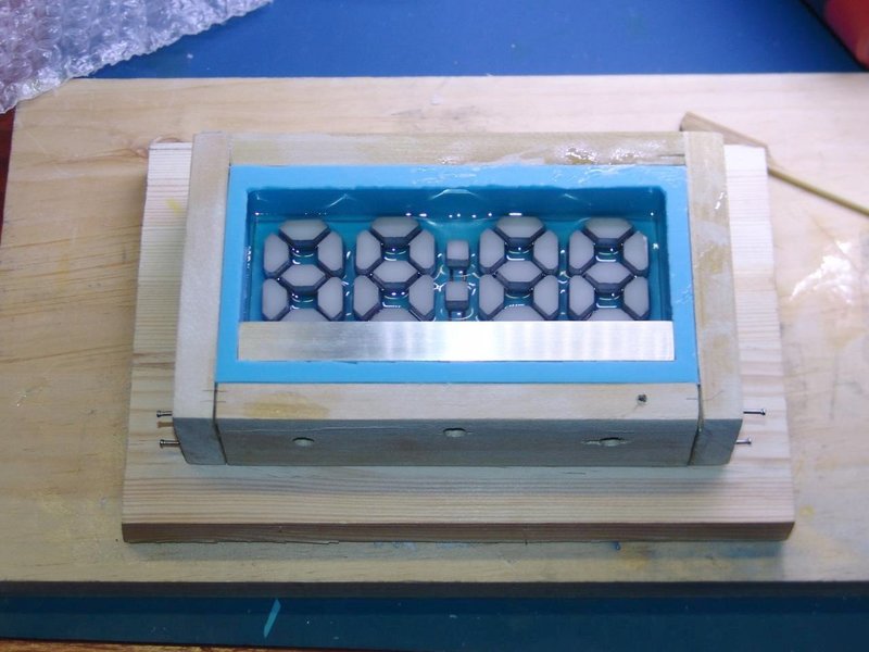
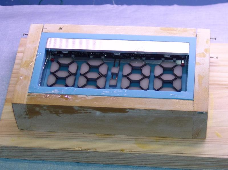
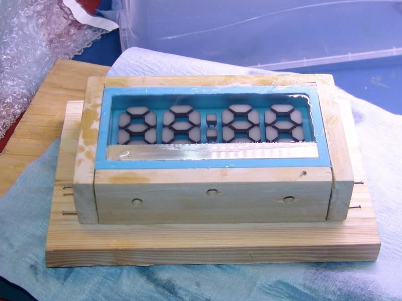
The mold was made in a way that I could fit the PCB inside it and pour the epoxy directly over the PCB. It did not work very well. Because the PCB is on top, the air bubbles get trapped under it and you cannot see if there is a problem until the epoxy is cured. Also, because the segments are so close together, it makes it impossible to paint the sides of the segments properly.
In the end, I casted the segments separately.
Assembly

I had to make a small cavity so that the LEDs could fit inside. I then glued each segment to the PCB using five-minute epoxy.
Display base
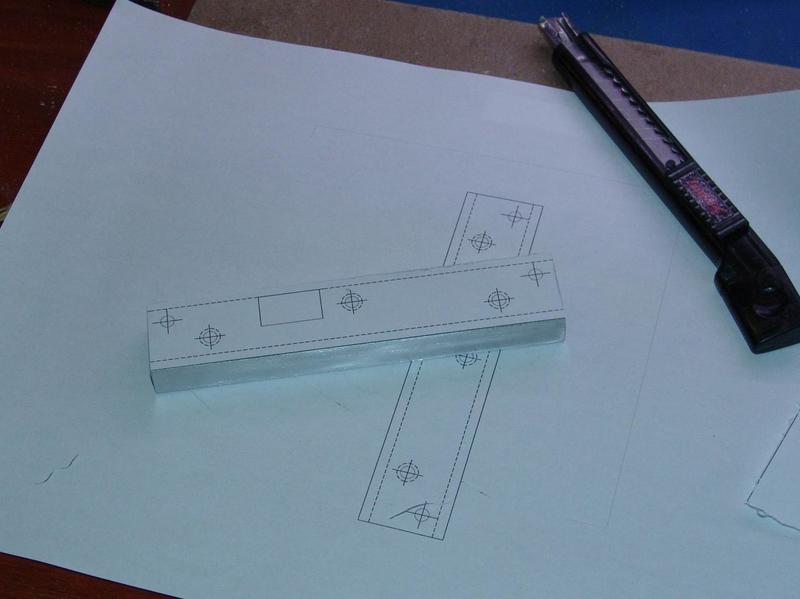
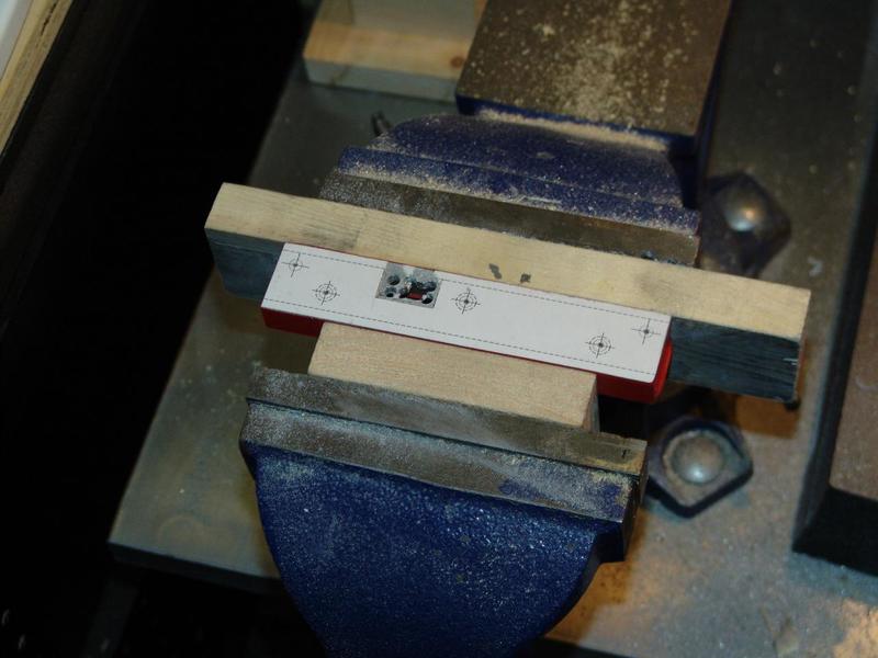
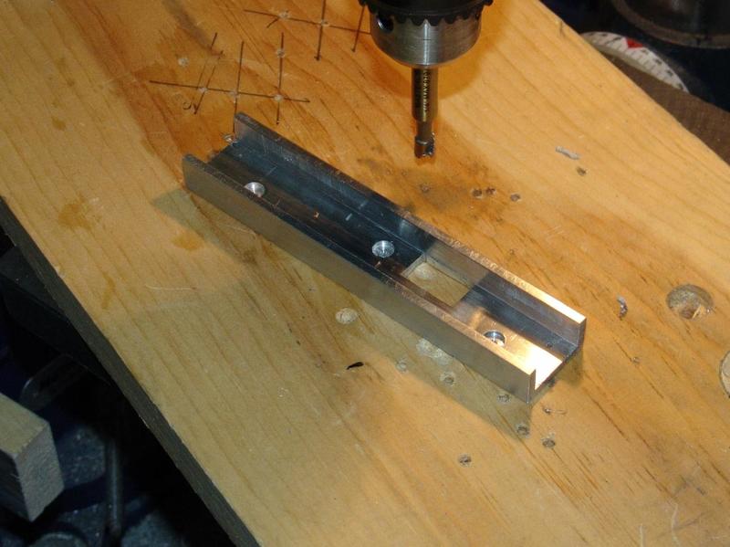
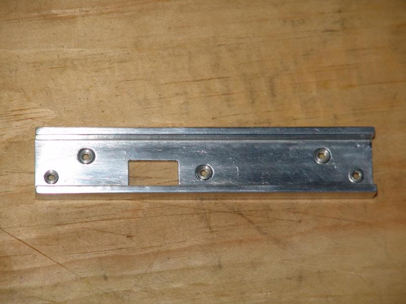
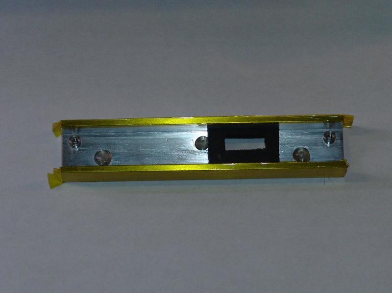

The base is made from a piece of 1 inch by 1/2-inch aluminum u-channel.
Encapsulating the display in epoxy
Moldel
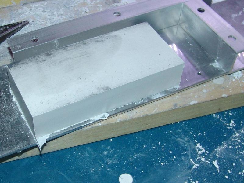
The first step was to produce a model (positive) for the silicon mold. I tried clay and polymorph plastic, but they both exhibited shrinkage problem when it dried (or cooled in the case of the polymorph plastic), the clay being the worst with 1/4 inch shrinkage over 5 inch. In the end, what worked the best was plaster of Paris with no shrinkage at all.
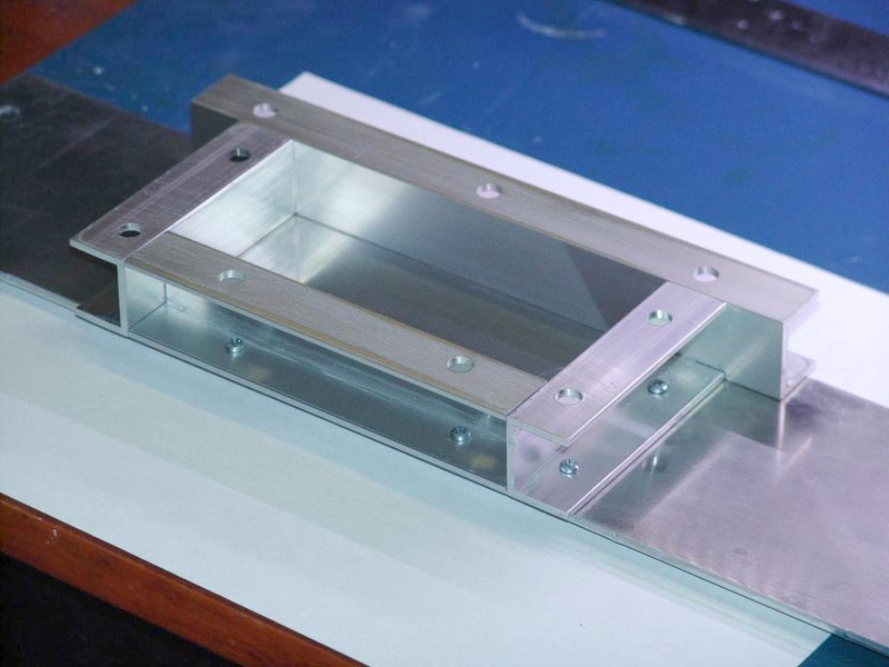
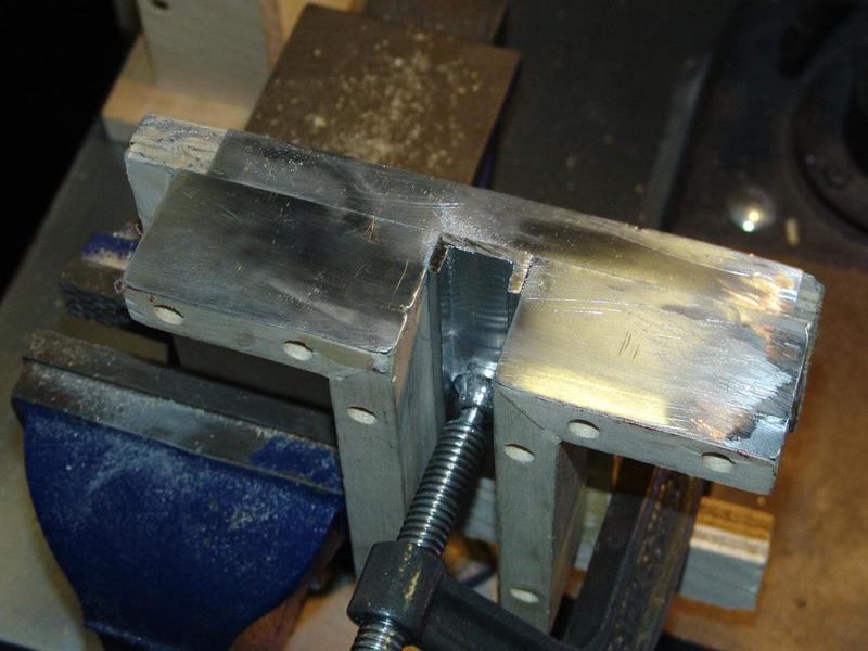
I constructed an aluminum frame using 1-inch wide u-channels. This is the first time I use plaster of Paris. I did not know if it would stick to the frame too much. To reduce the risk of cracking the model during de-molding, I sprayed a small amount of wd-40 on the frame, which acts as a release agent. I then removed the excess with a cloth. It came out perfectly, without cracking or chipping.
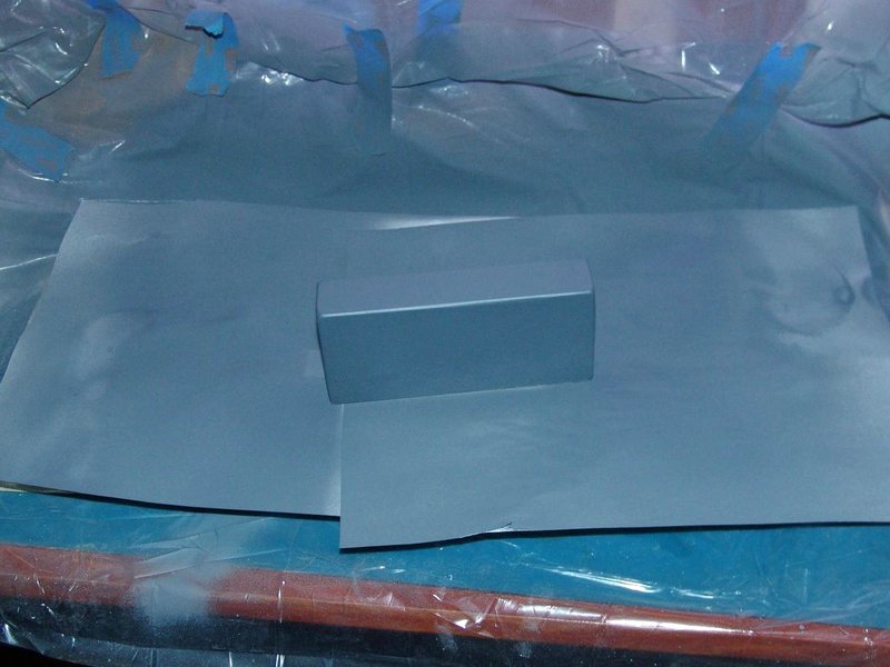
I then applied several coats of paint, sanding between each coat. I sanded the last layer with 2000 grit paper to make the surface as smooth as possible. This is important because any imperfections will be picked up by the silicon rubber and will show up on the final product.
Material
To make sure no epoxy would flow into the connector, I made a gasket with rubber foam and sealed the edges with silicon.
I was not sure whether to choose casting epoxy or polyester resin. I heard that you can achieve better results with polyester, but it produces a nasty odor while it cures. I live in an apartment, so I did not want to stink up the house for a week. It was winter at the time I made this so working outside was not an option either (especially with the crappy winter we had this year).
I opted for the Pebeo Gedeo crystal resin which I found at my local arts & craft supply store. It’s a mix of two parts resin to one part hardener and does not produce any odor while it cures.

Casting
I did a test run before trying to cast the final product. On the first attempt, I tried to pour the epoxy in a single one-inch thick layer. It produced a lot of heat and lots of bubbles. As I found out, it is much more difficult to get rid of micro bubbles when mixing large quantities of epoxy. The best way was to pour the epoxy in three layers waiting at least 12 hours between layers.
Special care must be taken while mixing. I mixed the epoxy for five minutes as slowly as possible to avoid introducing air bubbles in the mix.
I found a tip on the Internet for getting rid of bubbles which suggested placing the mixing cup in hot water for five minutes. I tried it and it seemed to help a bit. I know the proper way to ensure a bubble-free mix is to place it in a vacuum chamber, but I did not want to invest 150-200$ for a vacuum kit just for one project.
Poslishing
Epoxy resin fully cures in 24 hours but takes a few days before it becomes really hard. I waited two weeks before proceeding to sanding and polishing.
I started by sanding all surfaces by hand with a #120 grit paper until they were flush with the aluminum base. Then, I proceeded with #400, #1000 and #2000 grit and then, finished with 3M #3000 grit (wet sanding).


